Direction Finding
RSS direction finding began in 1938 when the G.P.O. created three new “U Adcock” d/f stations at Sandridge near St Albans, Stockland Bristol near Bridgwater and Cuper north of Edinburgh. They were built ostensibly as a peacetime development out of GPO’s own funds, but they were quickly formed into a military scheme by MI5 and the War Office. This was the first RSS radio activity. A concrete base still remains at Bridgwater and the station is visible in 1946 aerial photographs. In 1942 a second station was added in an adjoining field.
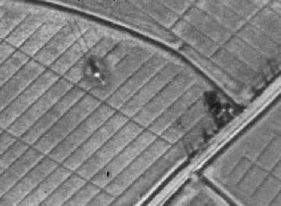
Bridgewater D/F Station 1946
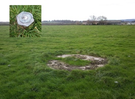
2009 and Concrete Base and 4 Feeders (see inset)
The original stations would have consisted of a central hut with four 10m high antennas at N,S,E&W. The feeders passed underground and came up in the centre of the hut and passed into a radio goniometer and from there to an HRO receiver. The operator received instructions from RSS HQ giving the frequency and the sound of the signal through the telephone line. This signal passed to one ear of his headphones and the other ear listened to his own receiver until he found the exact frequency. He them operated his goniometer to find a nul where the signals disappeared. He repeated this several times, took a mean of the measurements and passed it back the HQ d/f control room by telephone. The number of RSS stations quickly increased with installations at St Erth in Cornwall, Thurso on the North Coast of Scotland, Lydd in Kent and Gilnahirk in Northern Ireland.
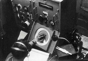
The early stations were all built and operated by the GPO an later when RSS was militarised many of the operators transferred to RSS who also recruited other operators from the Voluntary Interceptors such as Gerry Openshaw (G2BTO) who is seen below operating his d/f station in WW2.
Only a few photographs of the stations survive since they were top secret at the time and photography could have resulted in serious repercussions
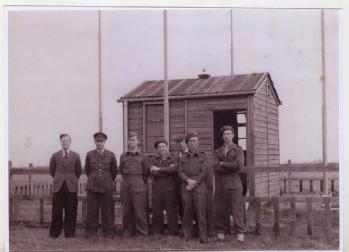
Lydd d/f station by courtesy of John McCafferty From the left –
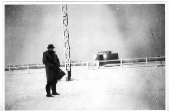
Thurso d/f station by courtesy of Gerry Openshaw G2BTO. The building shown was a six sided, double skinned wood construction with the cavity between the skins filled with shingle to make them bullet-
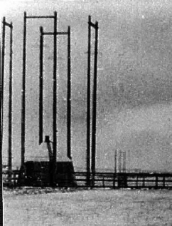
All the above stations mentioned were high frequency (HF or short wave) stations operating between about 2 Mhz and 30Mhz but RSS also operated medium frequency d/f stations on frequencies up to 3Mz. There were of a similar design but much larger with four 30m (100ft) high guyed lattice steel aerials. John McCaffetry is shown next to the lower part of one of the aerials at the RSS M/F d/f station at Lydd. In addition to the fixed stations RSS also had a fleet of mobile d/f vans located around the UK and subsequently taken into Europe after “D” day.
Spaced Loop D/F Stations
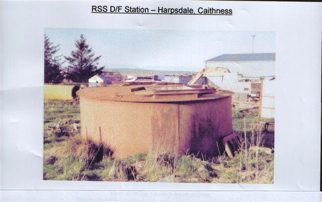
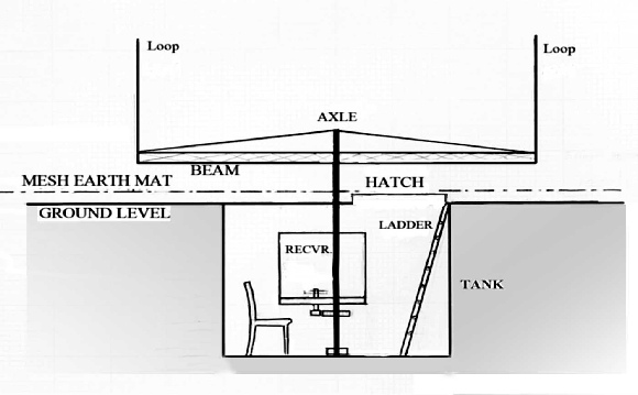
In November 1940, the then “Controller” Col. Worlledge placed an order with the GPO for seven new d/f stations of a new type called “Spaced Loop” recently developed by the National Physical Laboratory. There were designed to give much sharper bearings on transmitters at relatively short range (250 miles). The stations consisted of a rotating beam about 10m in length supporting a square loop at each end. The beam was rotated first and then a goniometer was operated to provide the final bearing. There was also another major difference, the operator was located in a large metal tank sunk into the ground directly below the aerials. While the development of experimental direction finder continued sites were chosen and metal tanks were installed at St Erth, Bridgwater, Wymondham Norfolk, Gilnahirk N.I. and Weaverthorpe Yorkshire. Of these only the Weaverthorp and Wymondham stations were installed. But by the time they were operating RSS had turned its attention to targets operated in Europe and the Spaced Loop system was unsuitable for such distant stations. Tests at Weaverthorp and Wymndham showed the signal stenghts were much reduced compared to the U Adcock stations and the Spaced Loops were abandoned by Mid 1942. In their place, RSS installed U Adcock stations keeping the underground tanks because of the protection they provided against aerial attack. One of the tanks excavated at the Clayock or Harpsdale station is shown below.
No photographs of the Spaced Loop stations have been located but the drawing opposite shows what they must have looked like.
Although the fixed Spaced Loop stations were abandoned, mobile versions were made and used later in Europe following the Normandy invasion.
D/F Reporting & Plotting
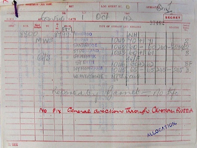
DF control was operated at both the Barnet HQ and Hanslope Park. The control room received bearings from the stations and recorded them on a d/f report form:
The results on the form were them plotted using a specially printed, foolscap size page, see below. It contained a map of Europe with the RSS d/f stations clearly marked and for each station there was a scale marked around the edge of the paper.
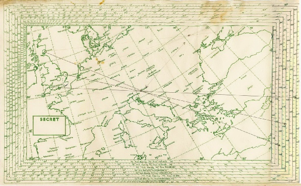
The plotter would then draw the bearing from each station using its own scale finally producing a crossing point at the origin of the transmission.
The RSS Telephone Network
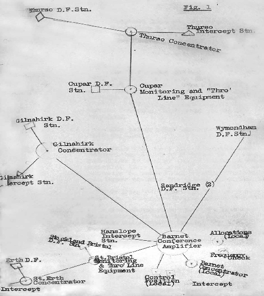
Perhaps the key to the success and speed of the operation was the telephone conference system that connected all the d/f and intercept stations with HQ using dedicated GPO lines, see diagram from the GPO archives below:
Click the LINK below to see a list of RSS direction finding stations with names and locations given in Latitude Longitude. Sites are either labelled “A” or “S.L.. A refers to Adcock d/f stations and “S.L.” refers to Spaced Loop d/f stations. In fact only two of the S.L. stations were actually built (at Weaverthorpe and Wymondham). The other stations marked SL were built as Adcock stations with underground tanks described above. No evidence has been found that any station was operated from Barwinnock. Co-
ST.ERTH (SL)
05° 23′ 15″ W 50° 10′ 00″ N
Map ref: Sheet 146 (England) X 008582
THURSO (A)
03° 33′ 03″ W 58° 33′ 27” N
Map ref: Sheet 11 (Scotland) D 630862
CLAYOCK (SL)
03° 26′ 25″ W 58° 31′ 00″ N
Map ref: Sheet 12 (Scotland) D 693814
CUPAR (A)
02° 59′ 22″ W 56 19′ 54″ N
Map ref: Sheet 64 (Scotland) O 892375
CUPAR (SL)
02° 59′ 30″W 56 19′ 50″ N
Map ref: Sheet 64 (Scotland) O 8893714
BARWINNOCK (SL) (see note 3)
04° 30′ 40″ W 54° 46′ 00″ N
Map ref: Sheet 91 (Scotland) X 868667
STOCKLAND BRISTOL (SL)
03° 03′ 40″ w 51° 11′ 74” n
Map ref: Sheet 120 (England) T 698659
ST.ERTH (A)
05° 24′ 45″ W 50° 09′ 40″ N
Map ref: Sheet 146 (England) W 990579
GILNAHIRK (A)
05° 49′ 16″ w 54° 34′ 29″ N
Map ref: Sheet 314 (Ireland) J 409720
WEAVERTHORPE (SL)
00° 31′ 40” w 54° 06′ 50” N
Map ref: Sheet 28 (England) A 438892
WYMONDHAM (SL)
01° O7′ 18″ E 52° 35′ 00″ N
Map ref: Sheet 66 (England) G 571212
SANDRIDGE (A)
00° 16′ 56″ W 51° 46′ 50″ N
Map ref: Sheet 95 (England) L 631301
Note1. This information was obtained from TNA file HW41/401
Note 2. (A)= Adcock, (SL)=Spaced Loop (anticipated) where the operator was located in a tank underground.
Note 3. Spaced Loop stations were only built at –
The other underground tanks were fitted with Adcock stations except Barwinnock which was never built.
Note 4. Map references refer to Cassini War Series maps. Conversion at http://www.fieldenmaps.info/cconv/cconv_gb.html
© The Secret Listeners
Website by CAMBITION